Dechorionator
Oregon State University
College of Agricultural Sciences
Department of Environmental and Molecular Toxicology
Sinnhuber Aquatic Research Laboratory

Summary
Timeline
Started
Joined SARL Engineering
Project Started
Initial Requirements Given
PCB Released: Dechorionator
Revision: 1.1.0
PCB Released: Dechorionator
Revision: 3.0.0
Project Finished
Delivered Units to Lab
Finished
Left SARL Engineering
Key Takeaways
- Created an all-in-one tool for removing the chorions of zebrafish embryos in a controlled and repeatable manner
- Developed custom PCBs to handle motion, pump control, and user interaction
- Deployed multiple units to the lab, and one to an east-coast partner laboratory
- Cost reduced to roughly 1/5 that of the lab's previous dechorionation hardware
Relevant Skills
Electrical
- Schematic & PCB Design
- Mentor Graphics PADS
- Altium Designer
- PCB Assembly & Rework
- Handheld Soldering
- Handheld Hot-Air Reflow
- Oven Reflow
- Electrical Diagnostics
- Multimeters
- Oscilloscopes
Software & Environments
- Git
- Programming
- Low-Level Embedded C/C++ (Atmel Studio)
Details
Before delving into what was built, some quick context is probably
needed. A dechorionator is a device that removes chorions from embryos. Chorions are the outer membranes of an embryo which provide
protection, and a permeable membrane which can allow gasses and nutrients
to reach the developing animal inside. As SARL is a toxicology lab, and its
experiments need to be deterministic, this protective layer can drastically
skew tests results, and even worse, can can variances embryo to embryo, or
egg batch to egg batch. To remove this, a special protein is added to a petri-dish
full of embryos, and then the dish is gently swirled with jerking start and
stop motions. The goal is to provide light agitation between the embryo, the
dish, and their neighbors, helping the protein eat away the chorion and sluff
off into the dish. This can, and has been done by hand, but when I joined
SARL they already had two machines which which could automatically perform
this task. However, they were incredibly expensive and massively overcomplicated,
requiring a whole table's worth of custom shaker units, networked peristaltic
pumps, and servos. The engineering team was tasked with simplifying this setup
while reducing both their size and cost.
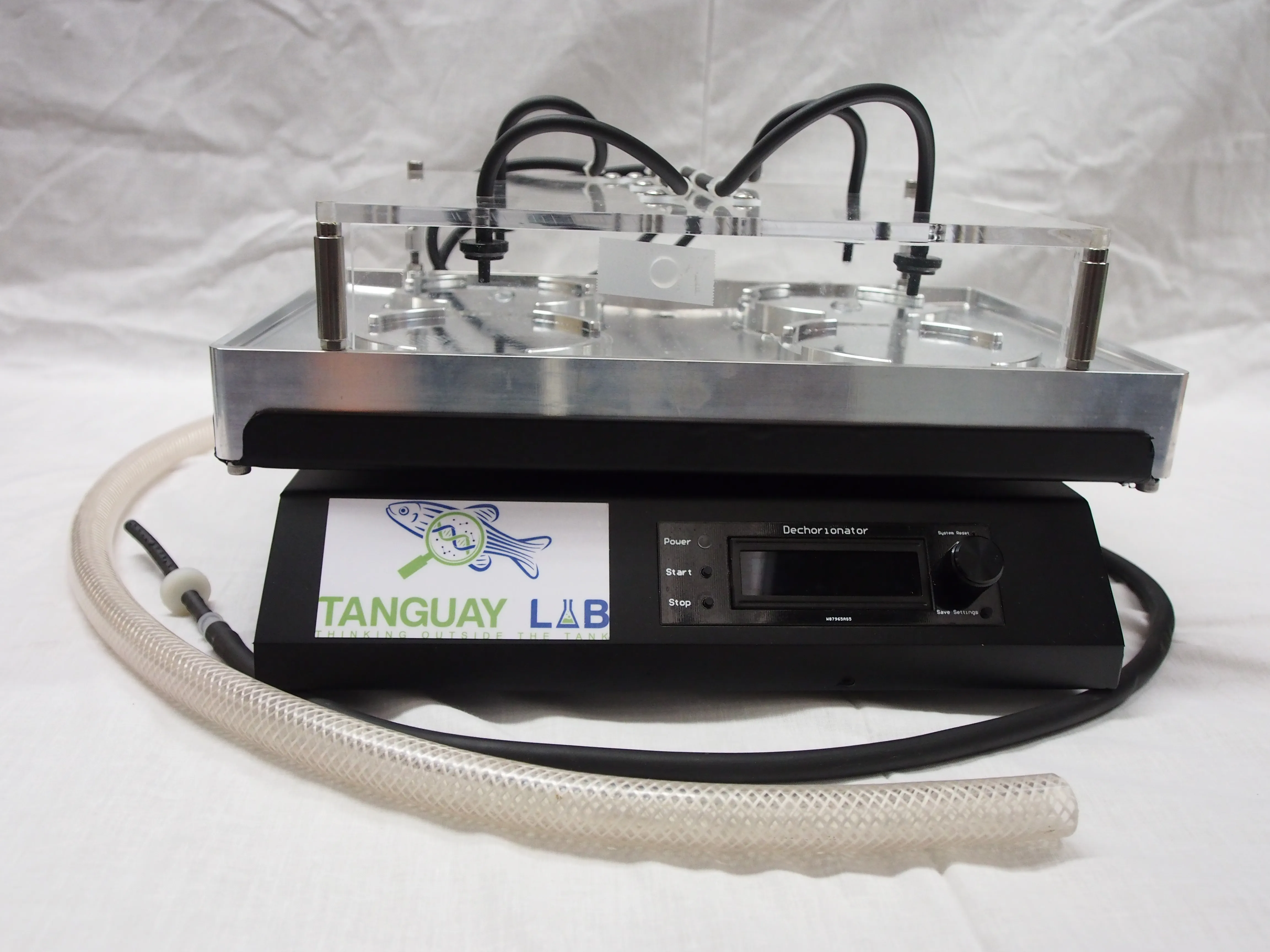
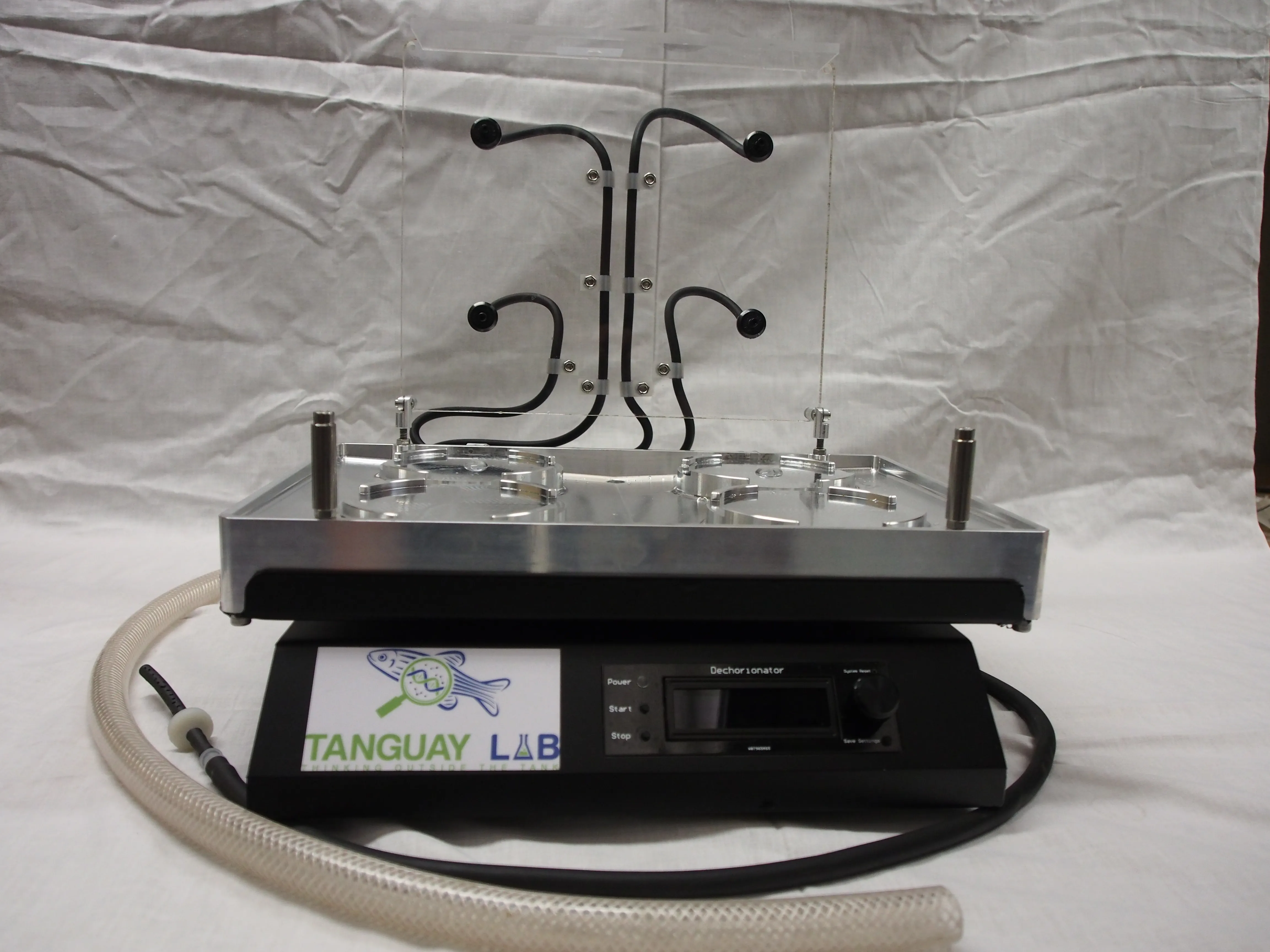
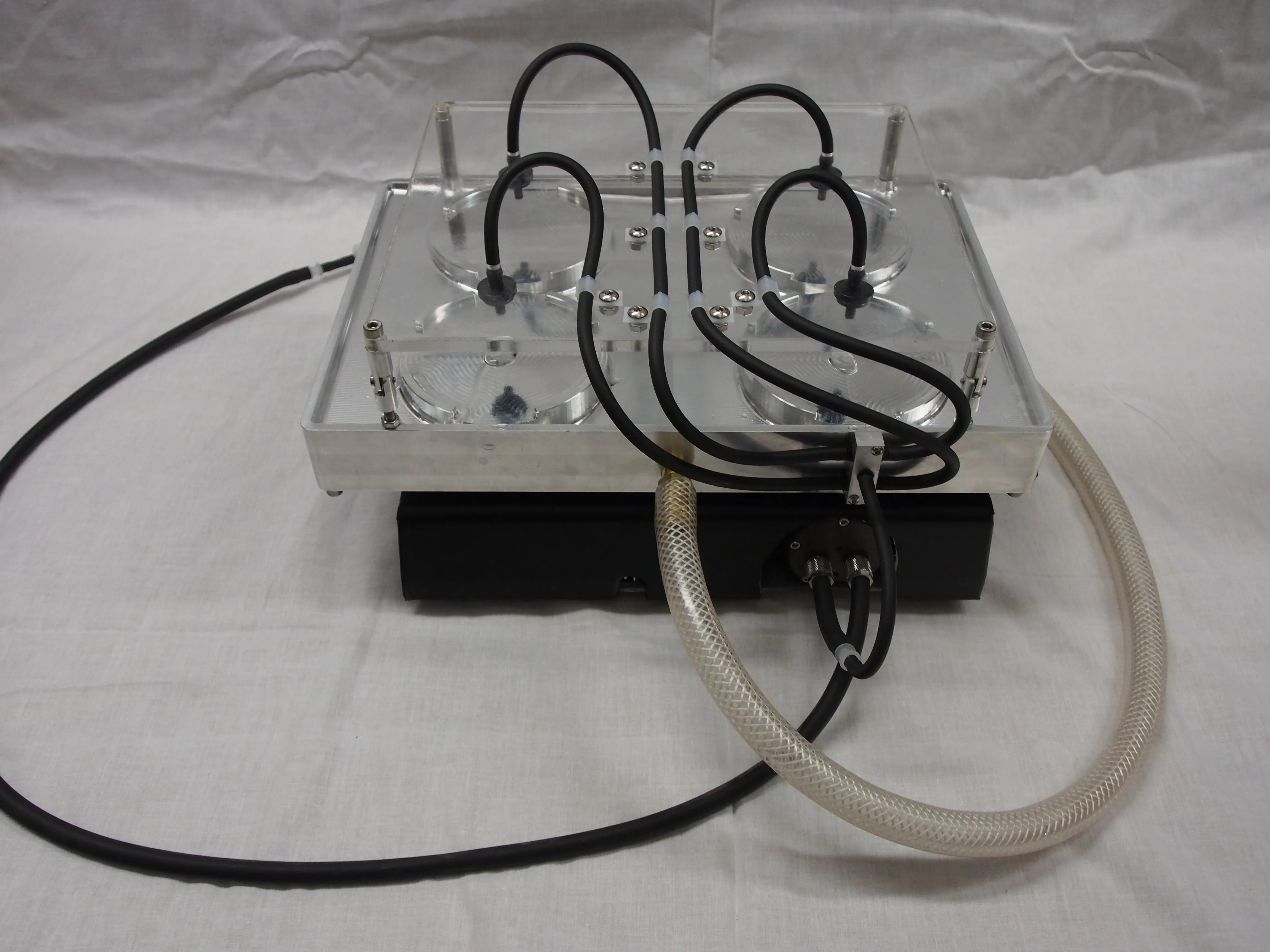
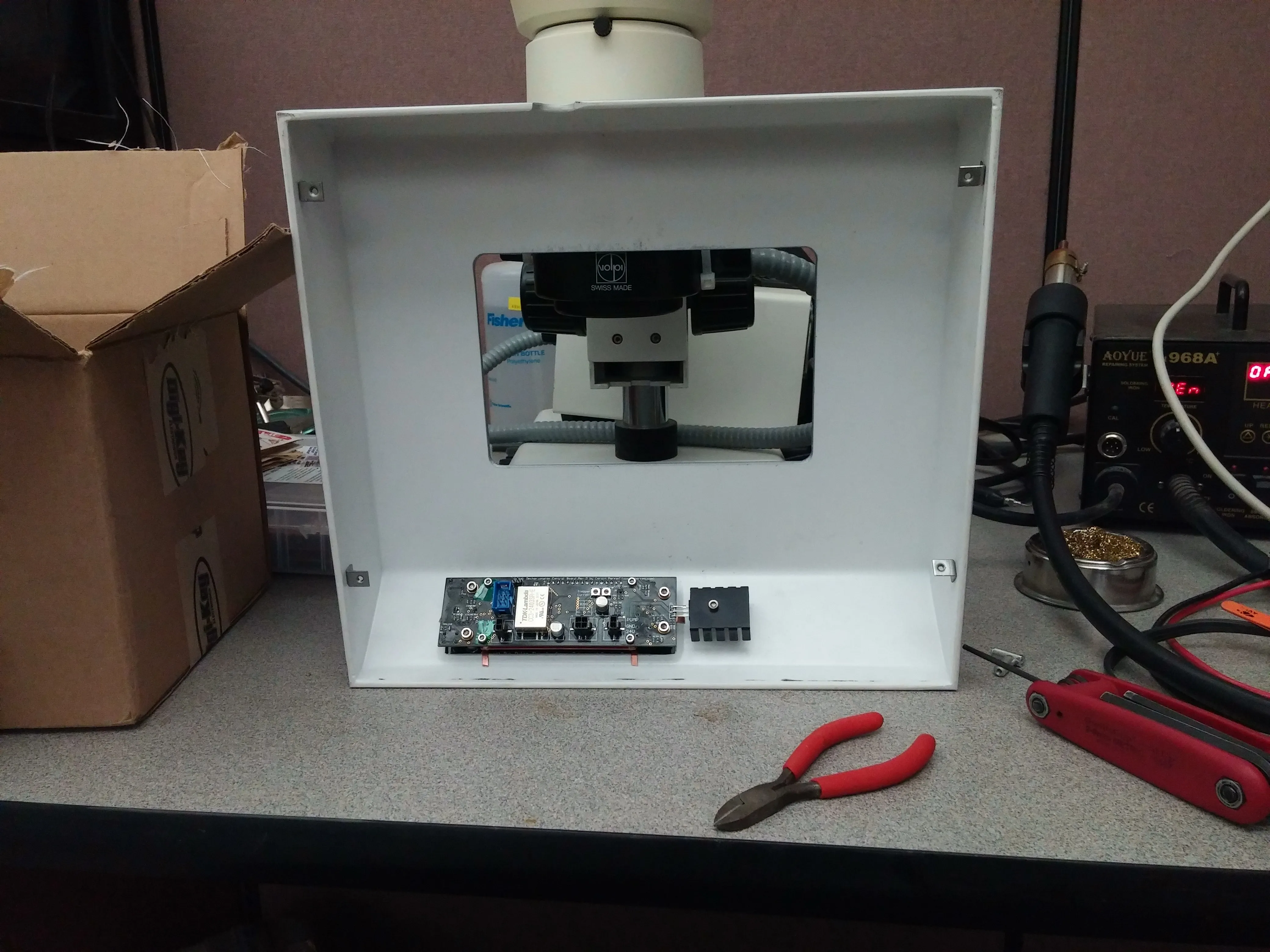
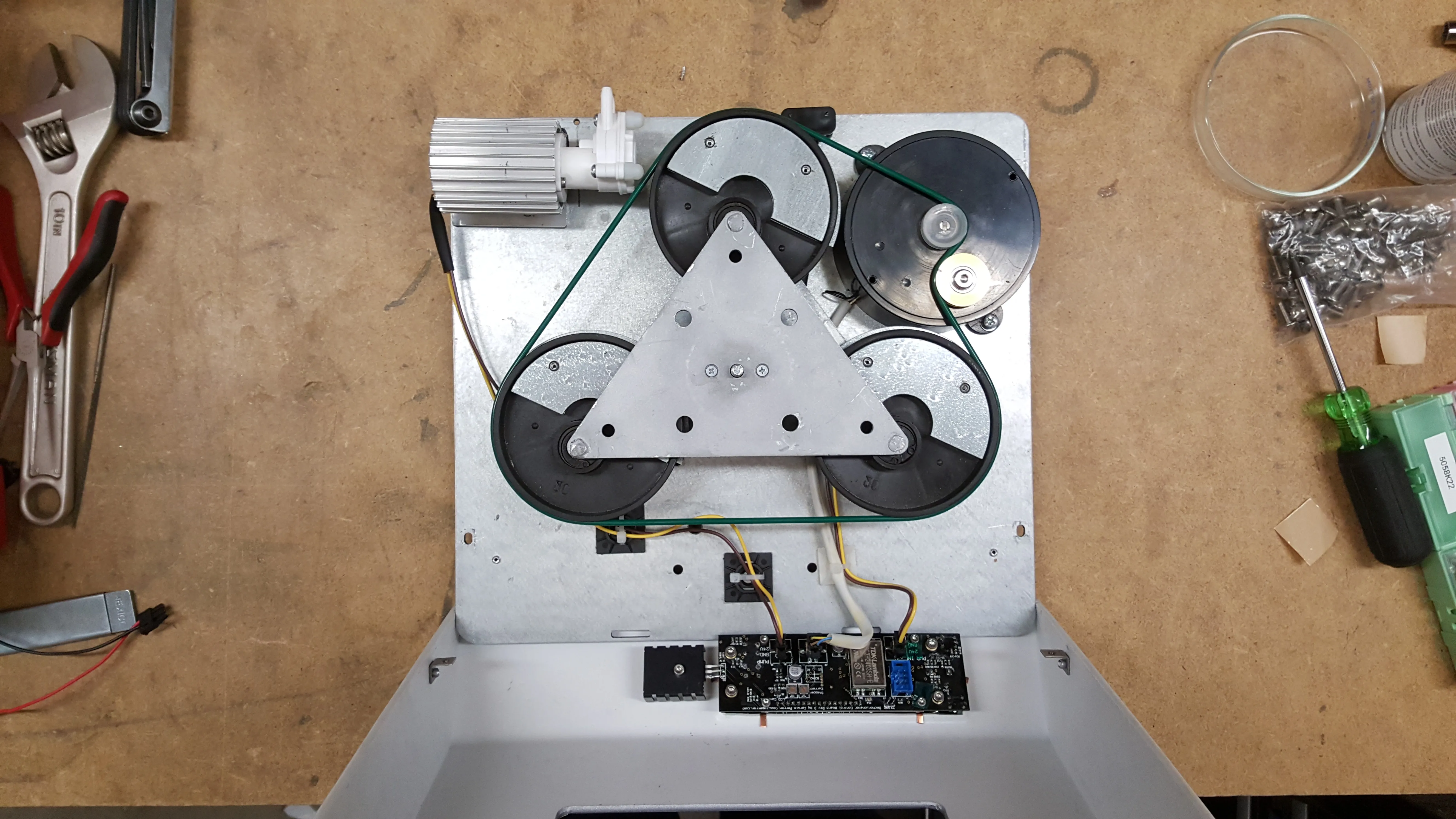
We started with a COTS shaker unit from the
company ELMI, which had a stepper-motor-based drive system, making it a perfect
candidate for easy retrofit. After gutting the existing electronics, and taking
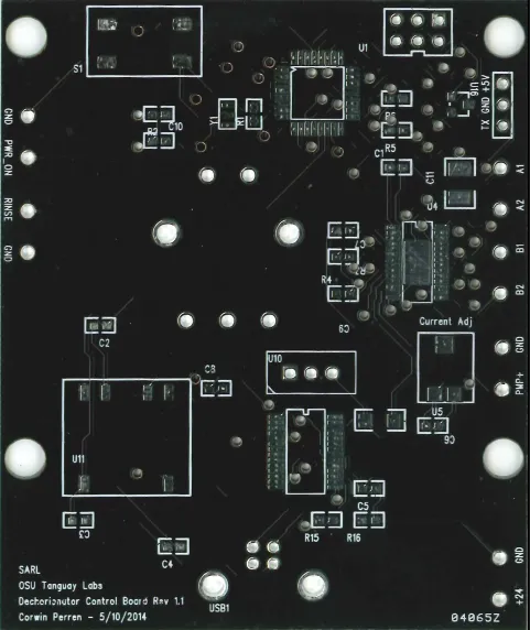
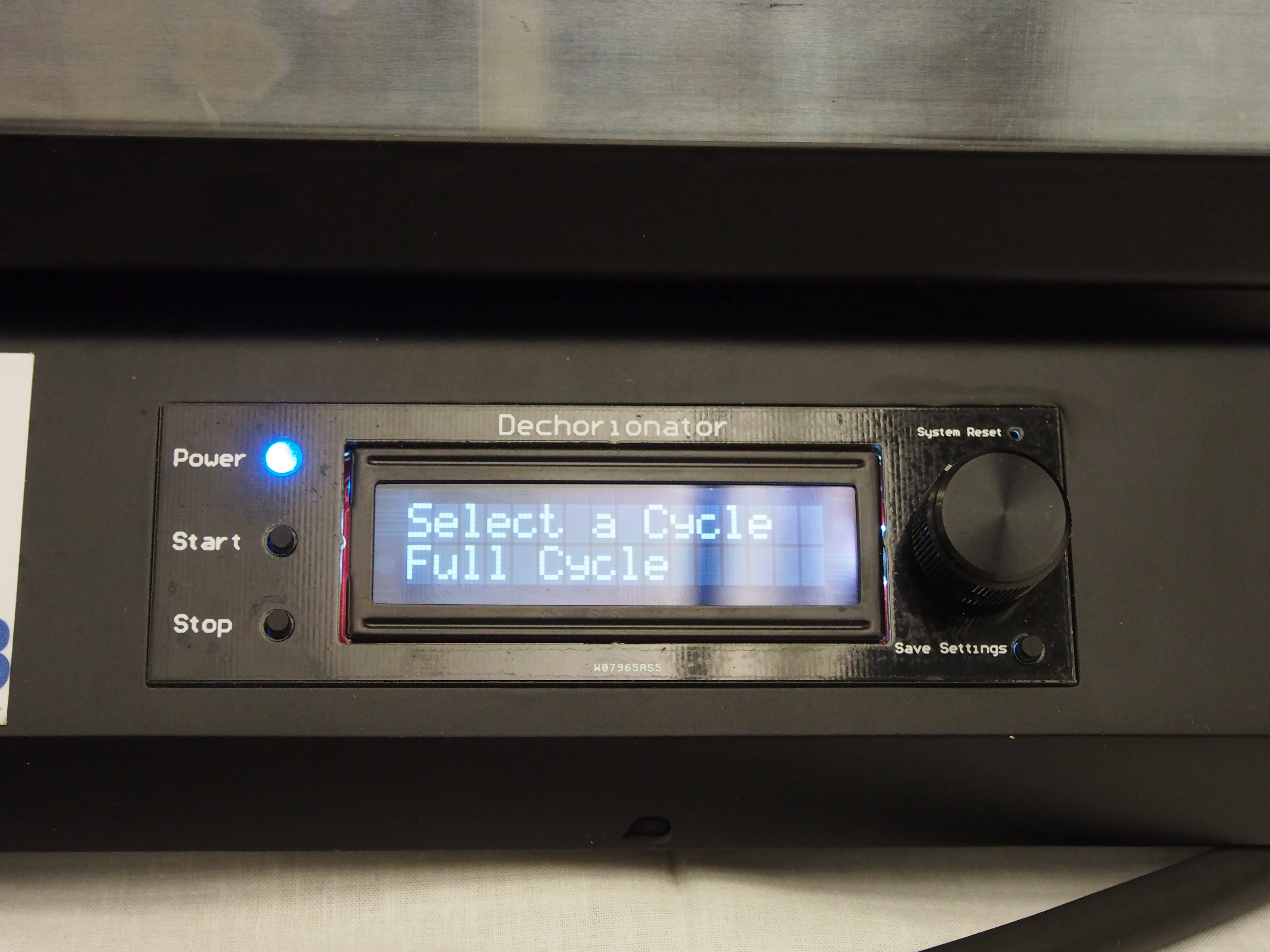
some measurements, I started on a custom PCB design. Basic requirements were
that the board needed to be able to control the stepper motor, control the
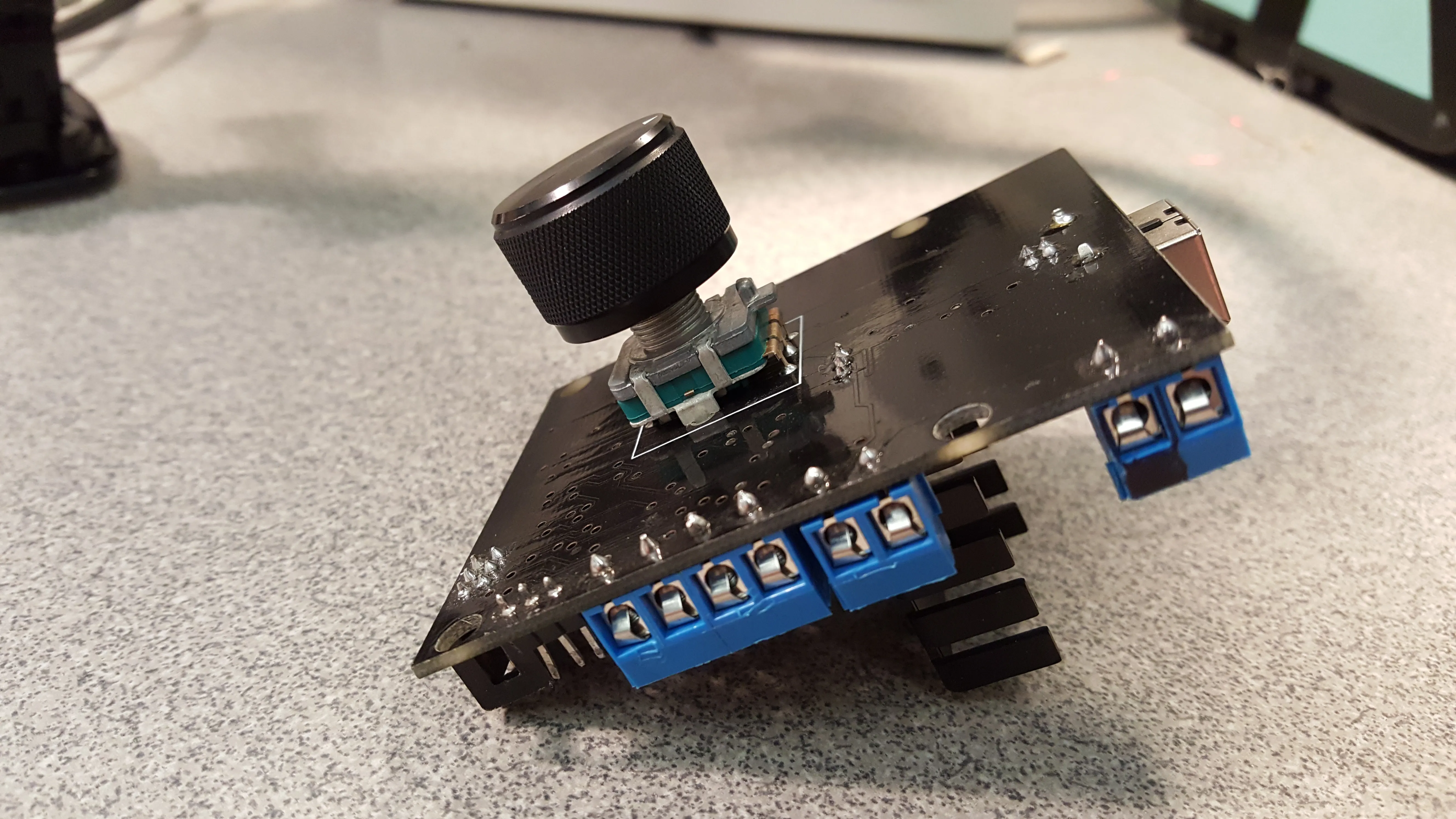
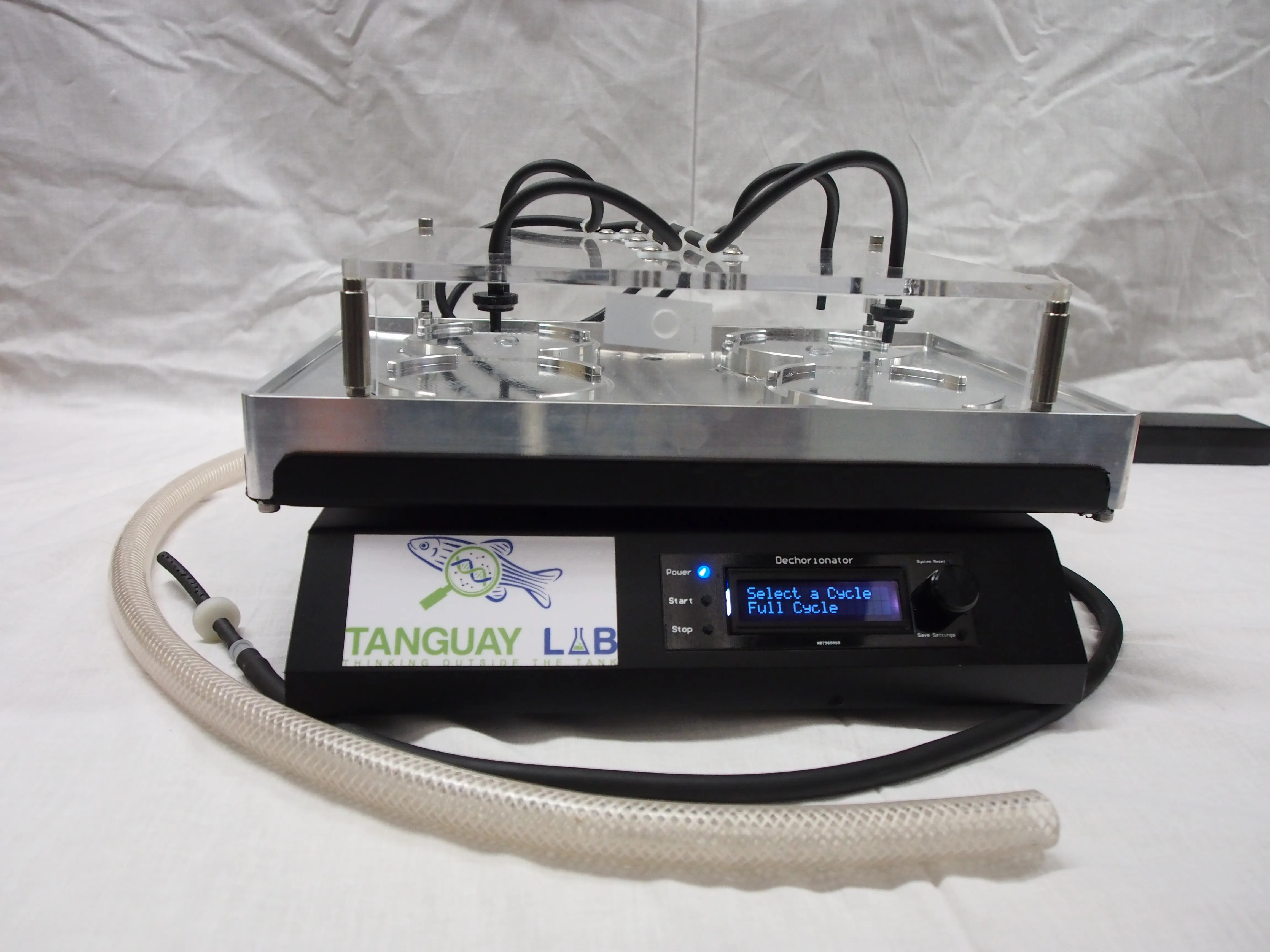
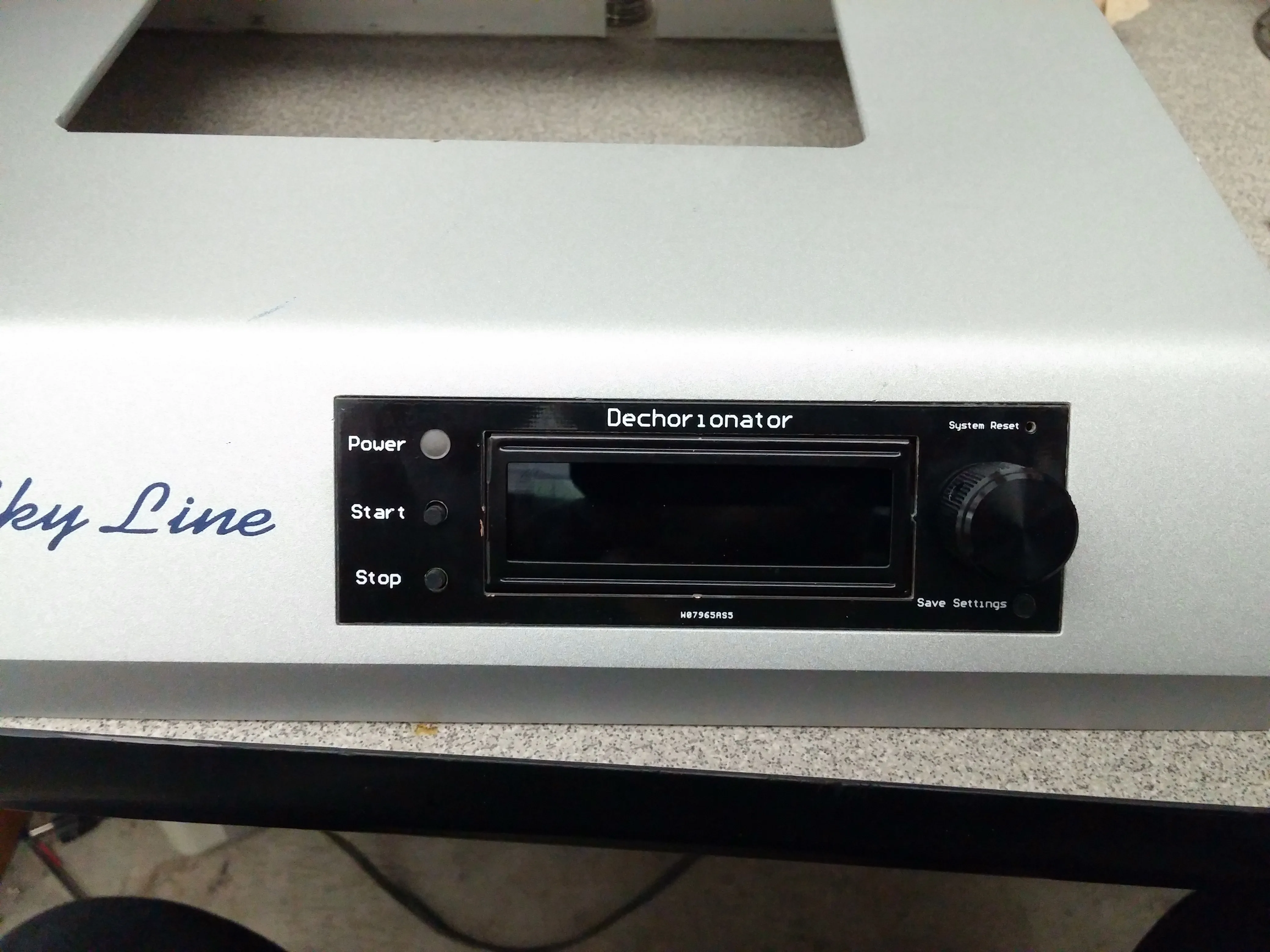
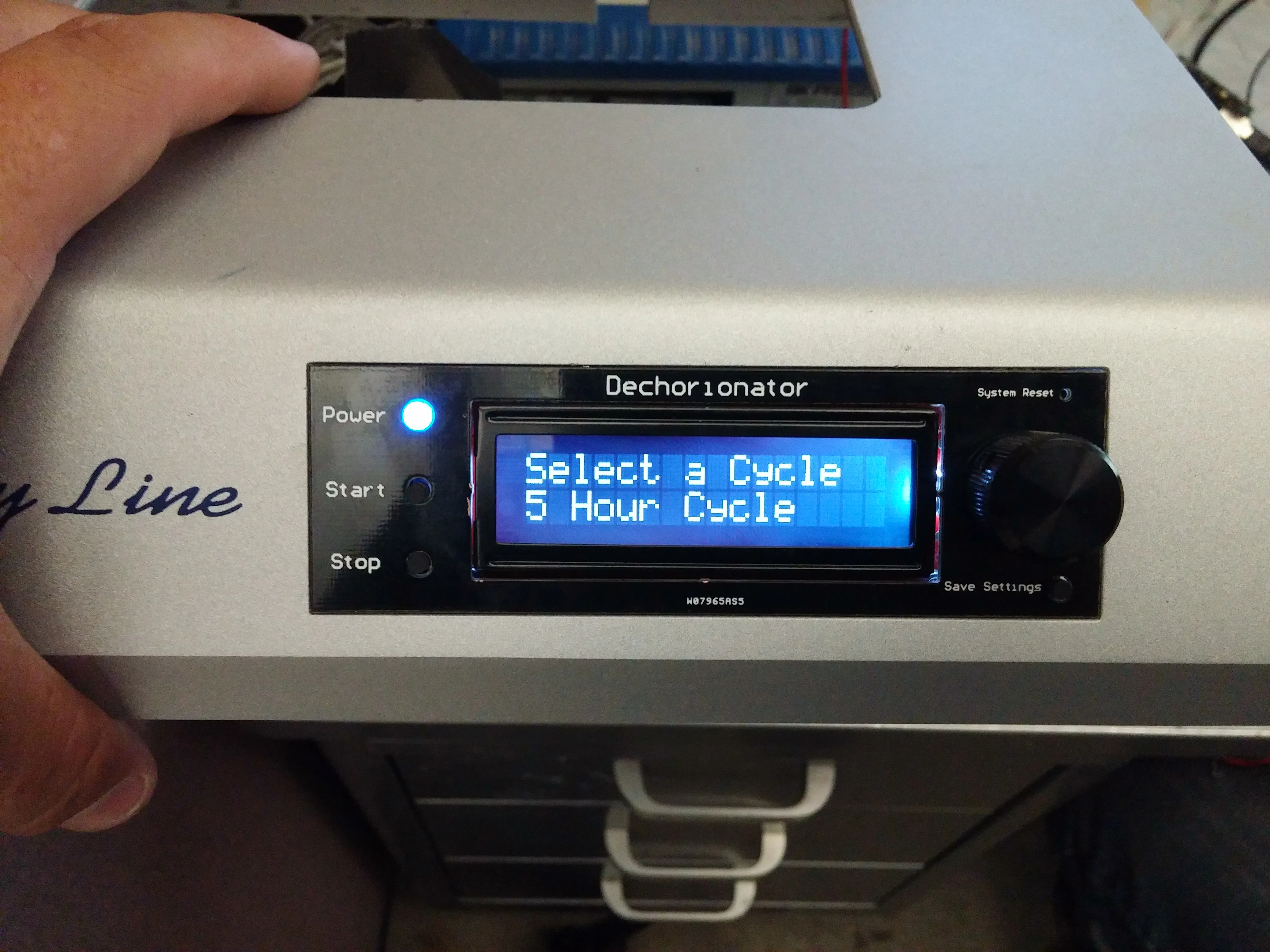
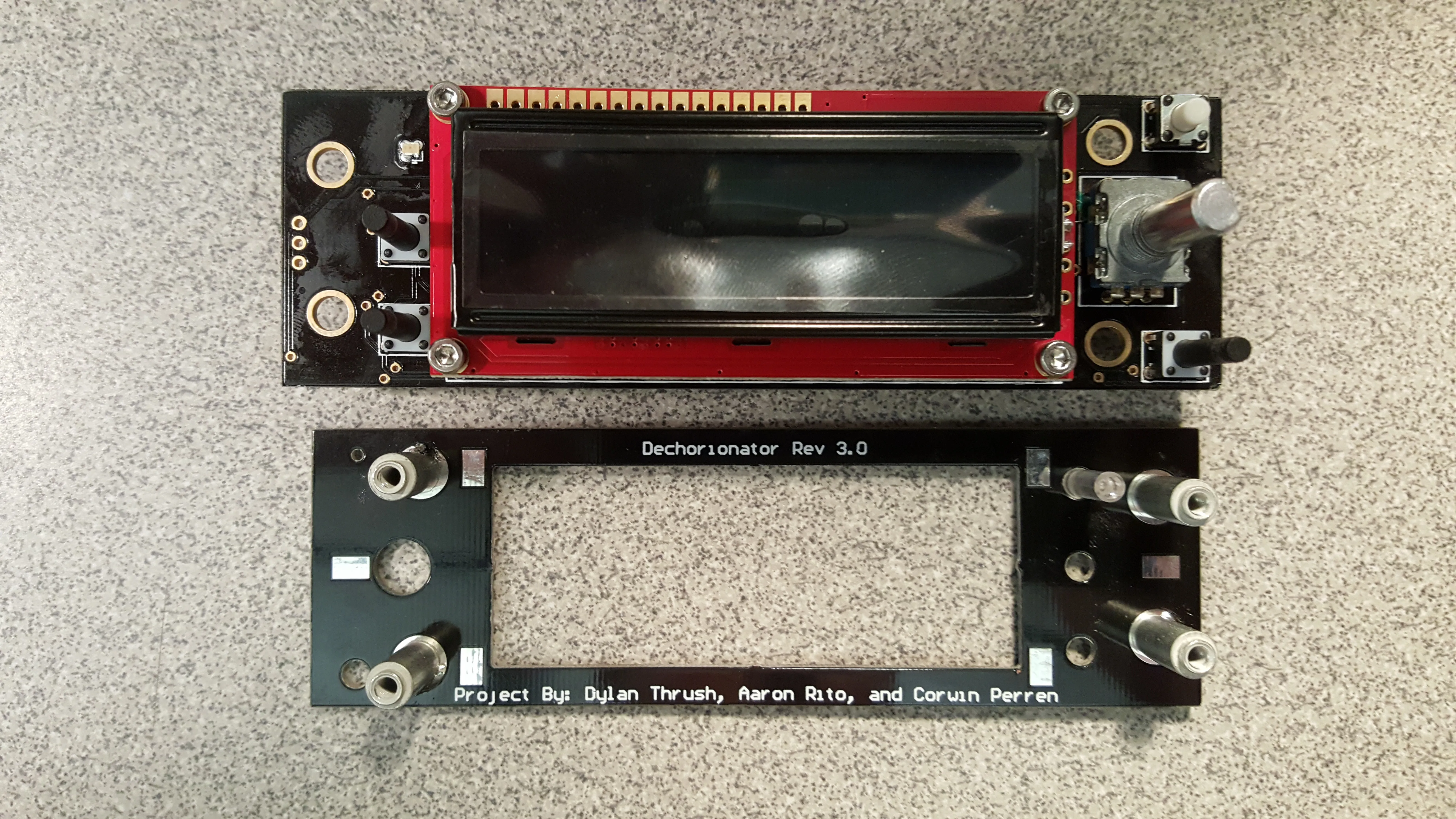
speed of a liquid pump, provide controls to users, allow for config editing
from those controls, and provide a screen for cycle progress and editing those
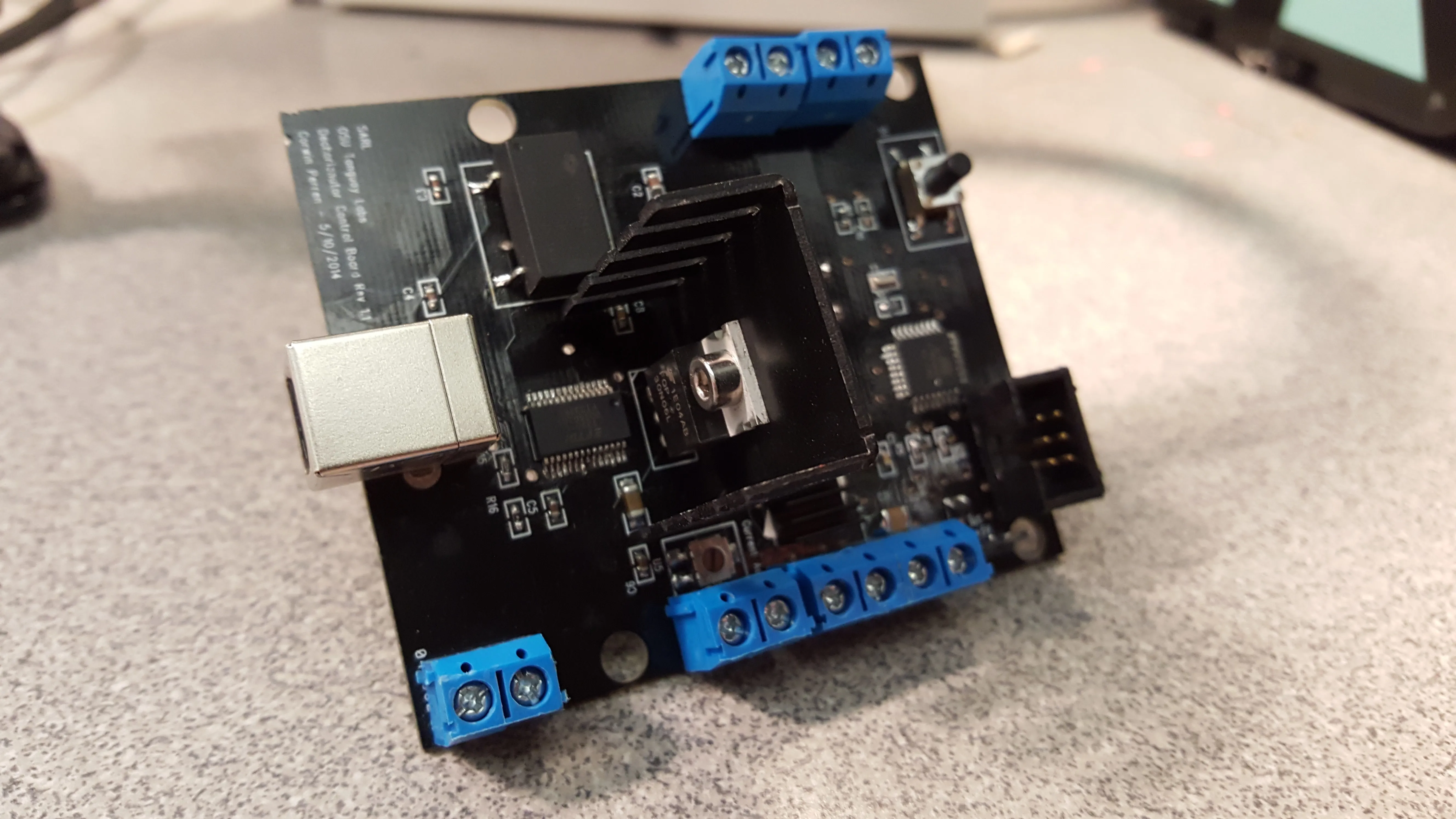
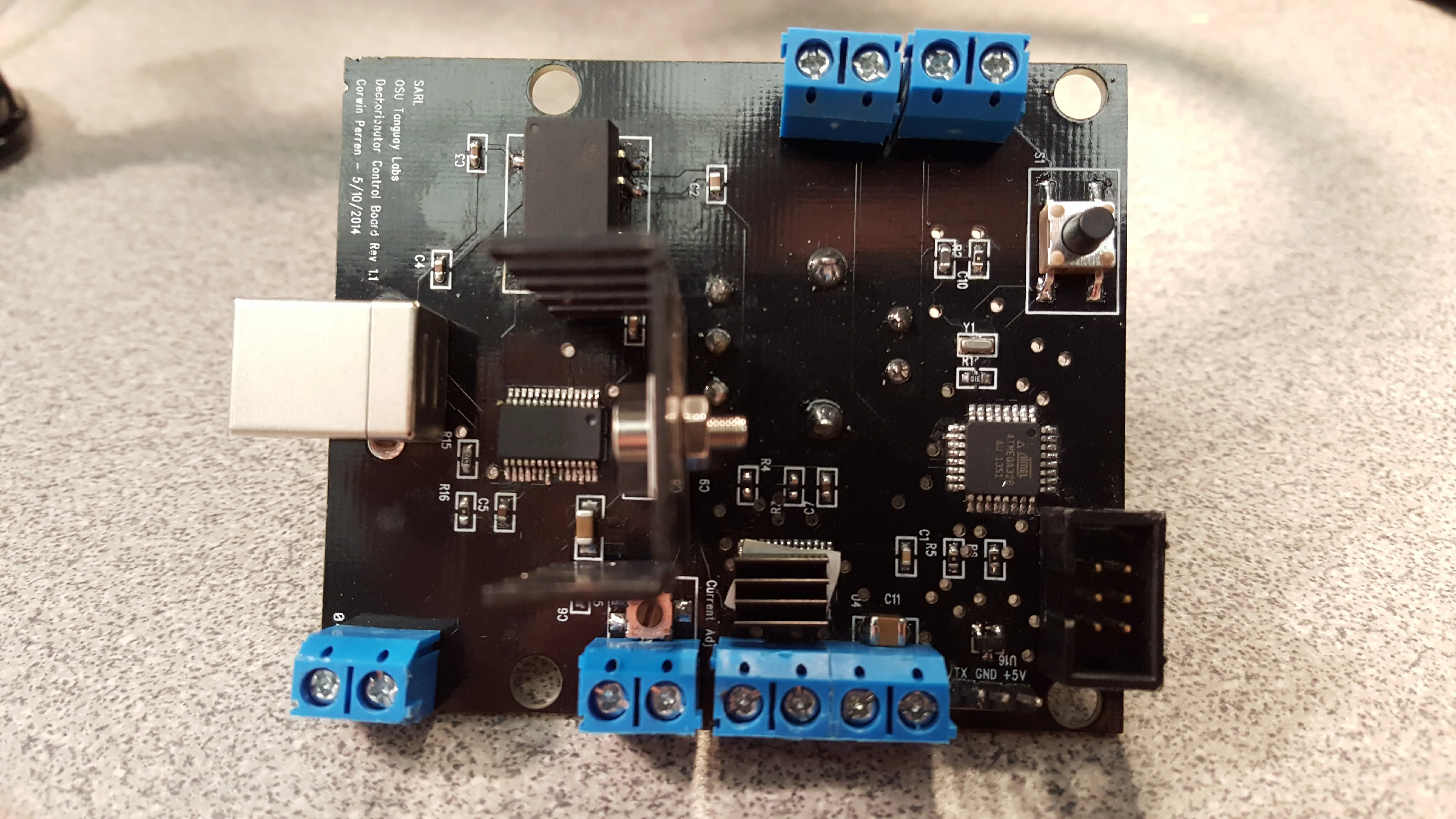
config values. Since this was one of the first PCBs I'd ever designed and
hand-assembled, I started with a basic proof-of-concept which was for bench
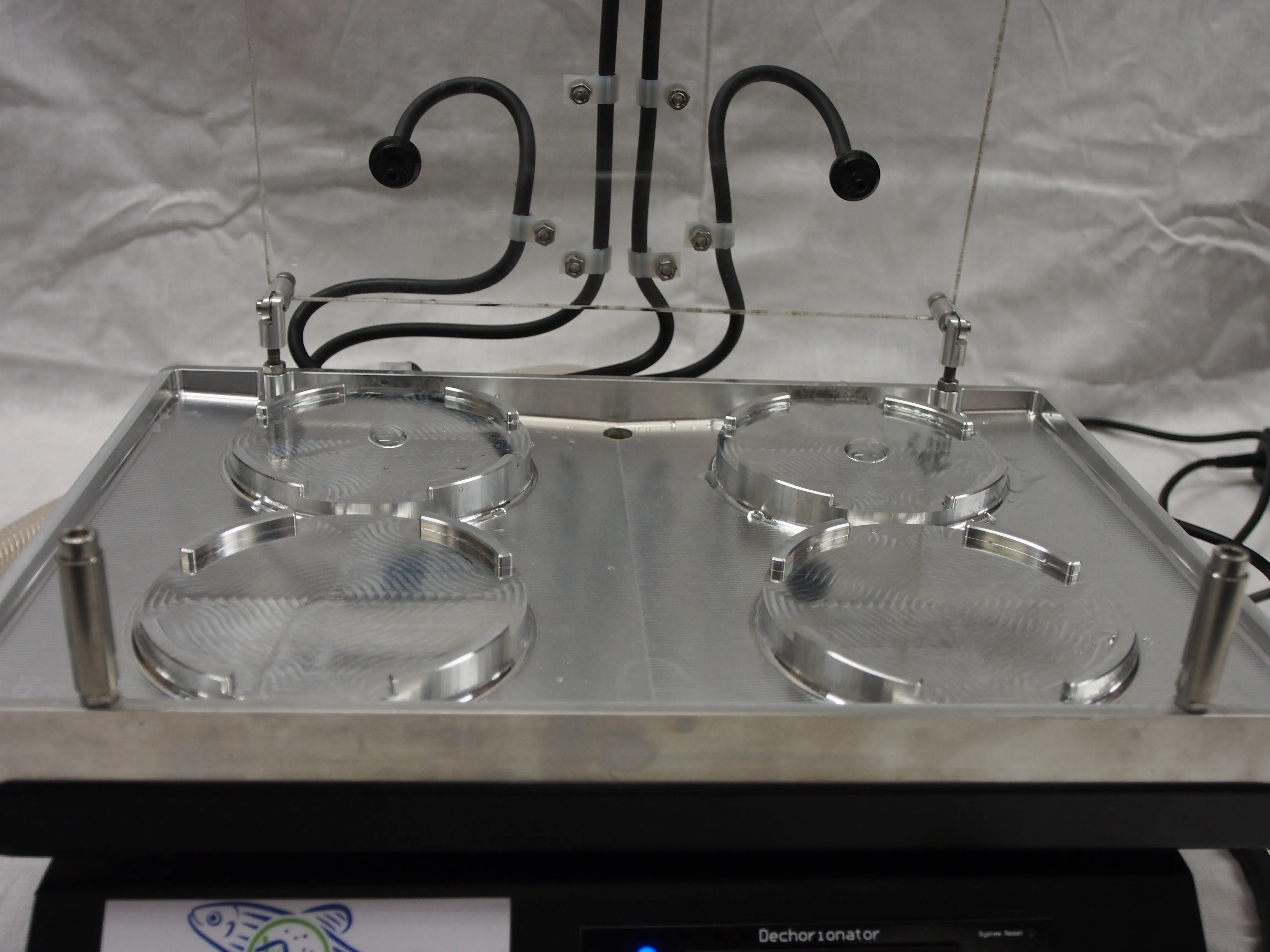
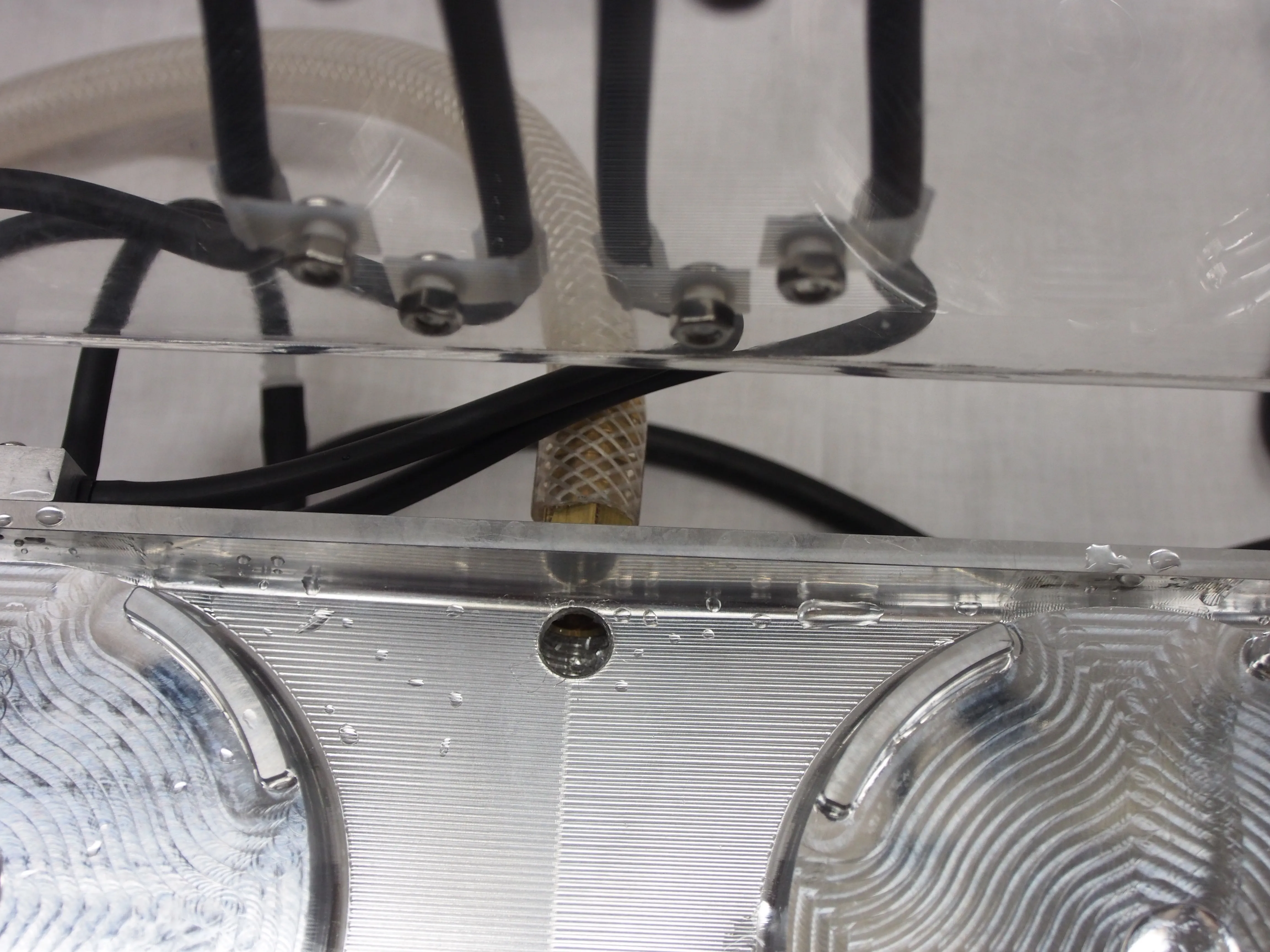
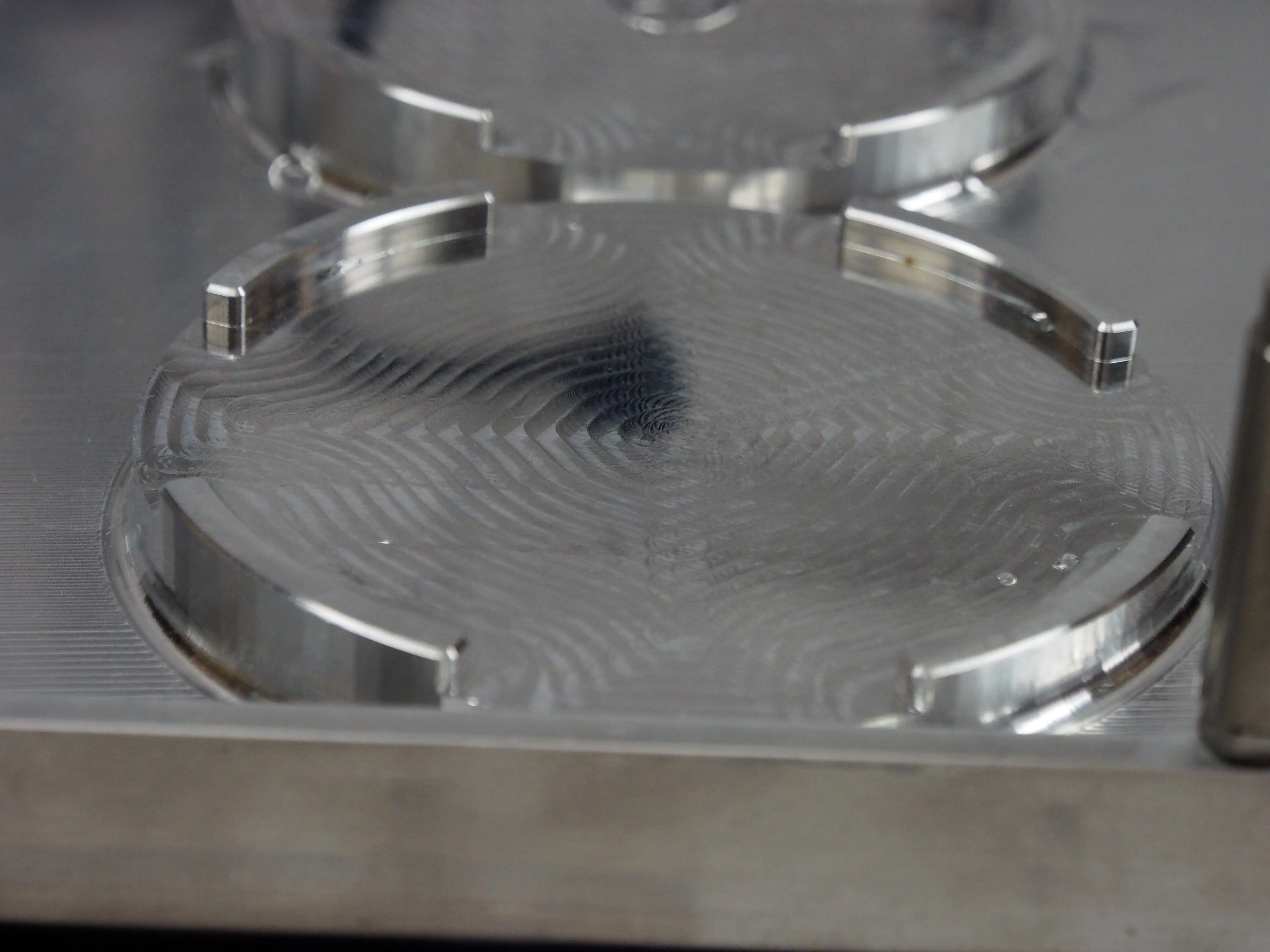
use only (revision: 1.1.0). While I worked on the electronics, my co-worker
and good friend Dylan Thrush was busy designing a top-plate for the shaker to hold the dishes, shower
them with water, and drain the pumped-in liquid.
COTS
Consumer off-the-shelf
First tests showed that the overall concept was going to work, just
needing signal conditioning for the rotary encoder to avoid ghosted or
missing inputs. A larger problem we found was that the brushed-dc-motor
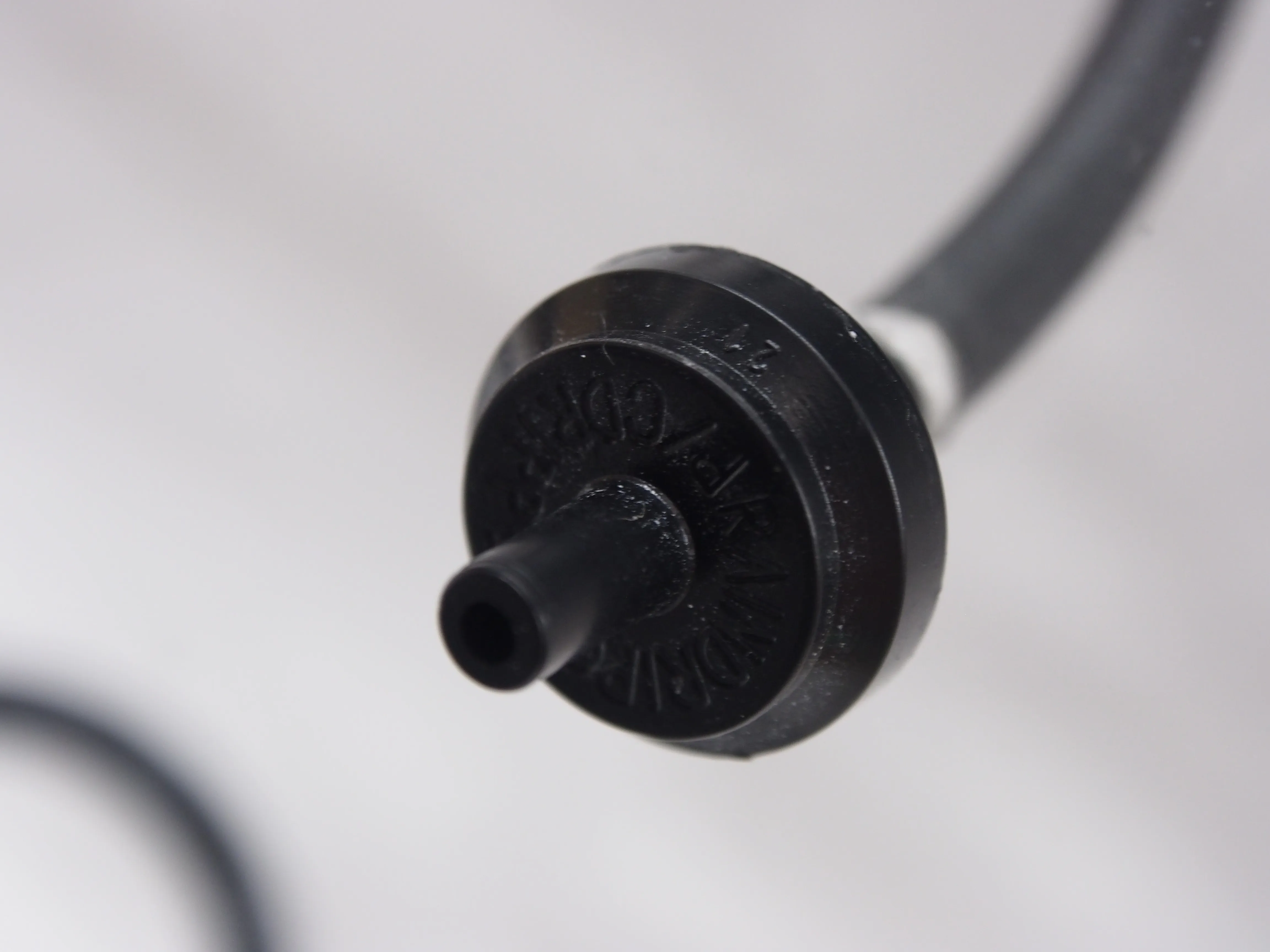
driven peristaltic pump was not going to be able to supply the flowrate
needed to properly shower the four dishes. We'd already chosen one of
the highest-flowrate pumps which could fit inside the shaker housing,
and ended up having to pivot to a much more expensive one from TCS
Micropumps. Luckily, not only did it solve our flowrate problem, but
also held up much better to the saltwater solution being pumped through
it than our initial choice.
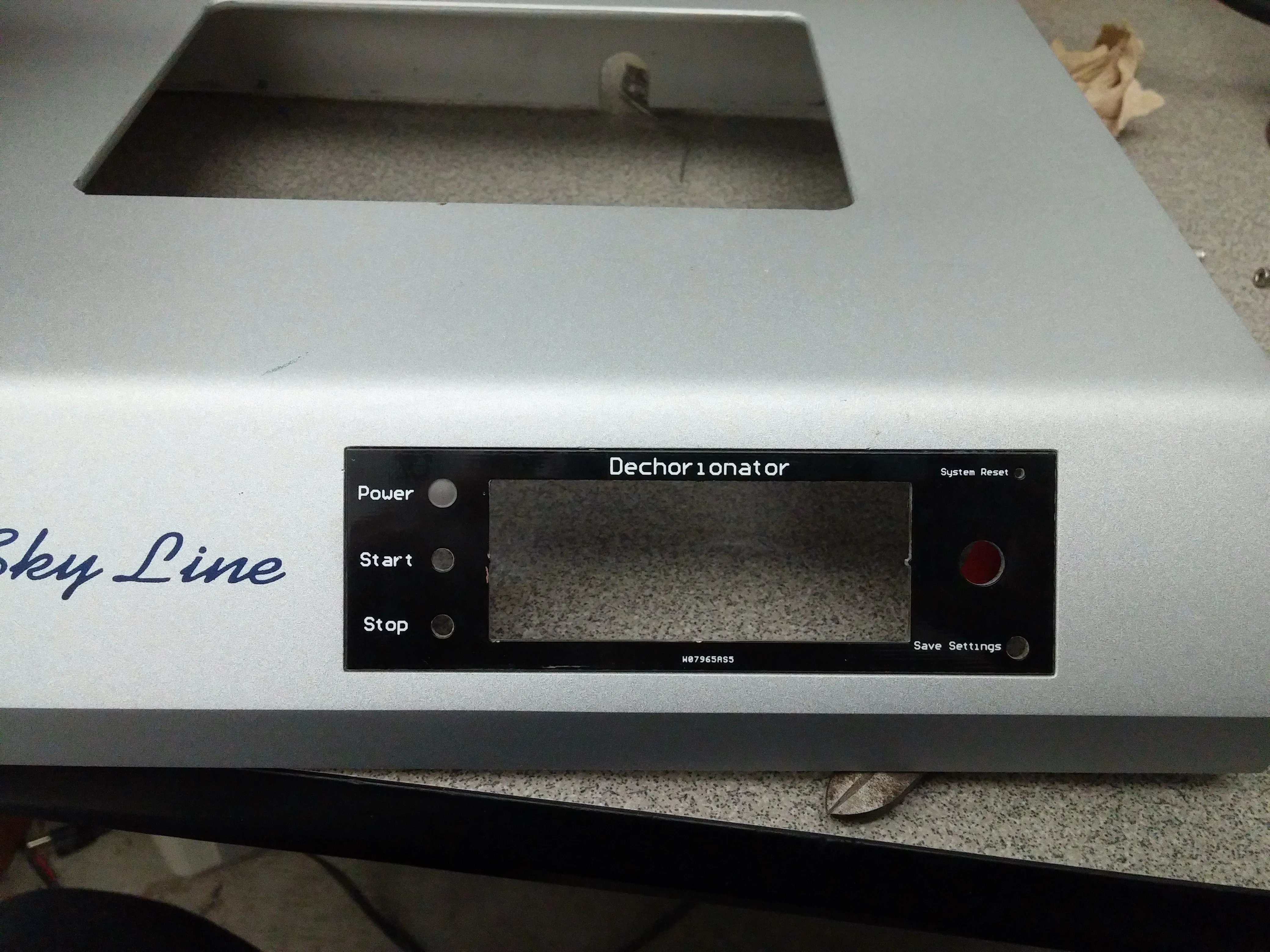
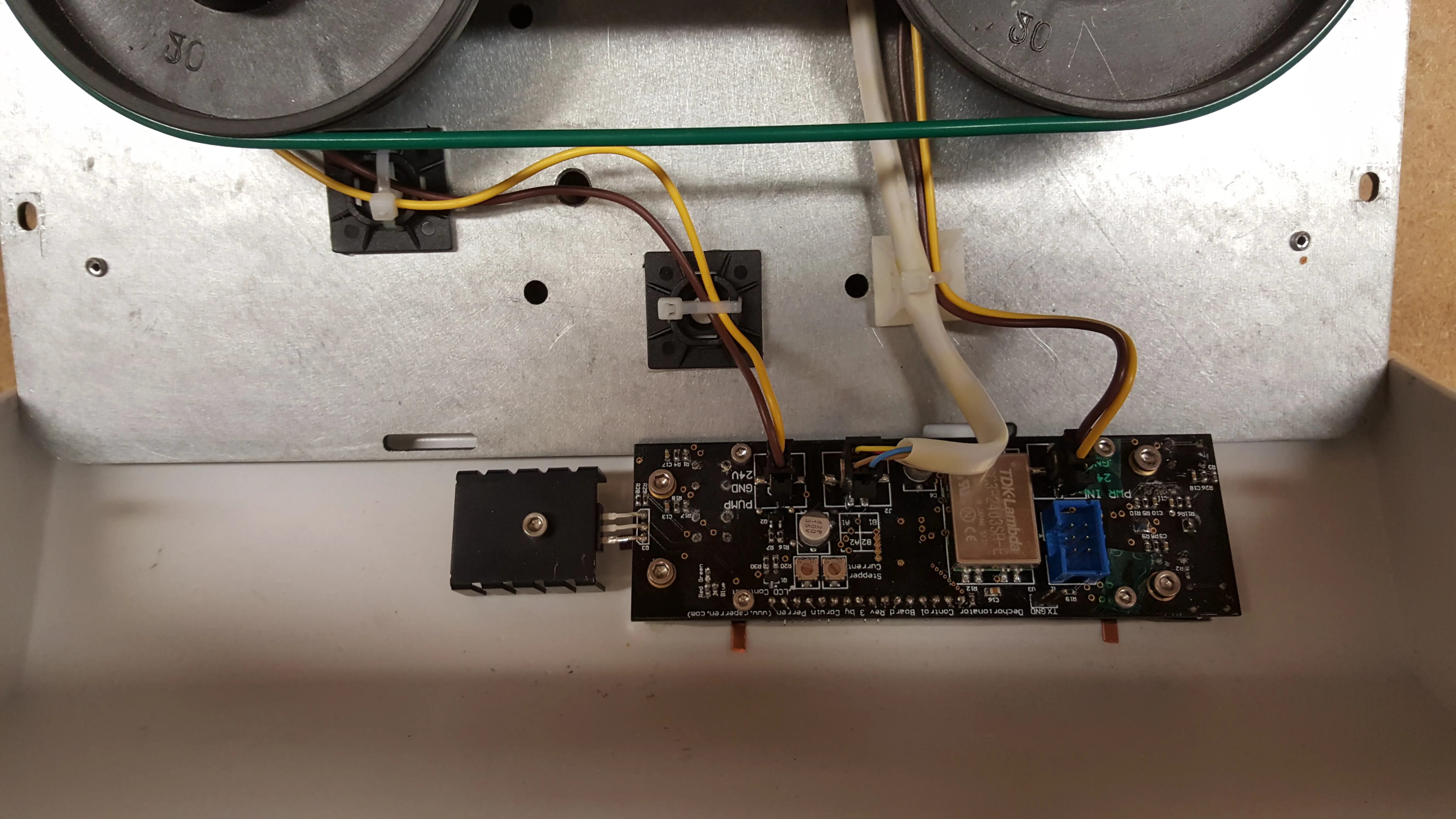
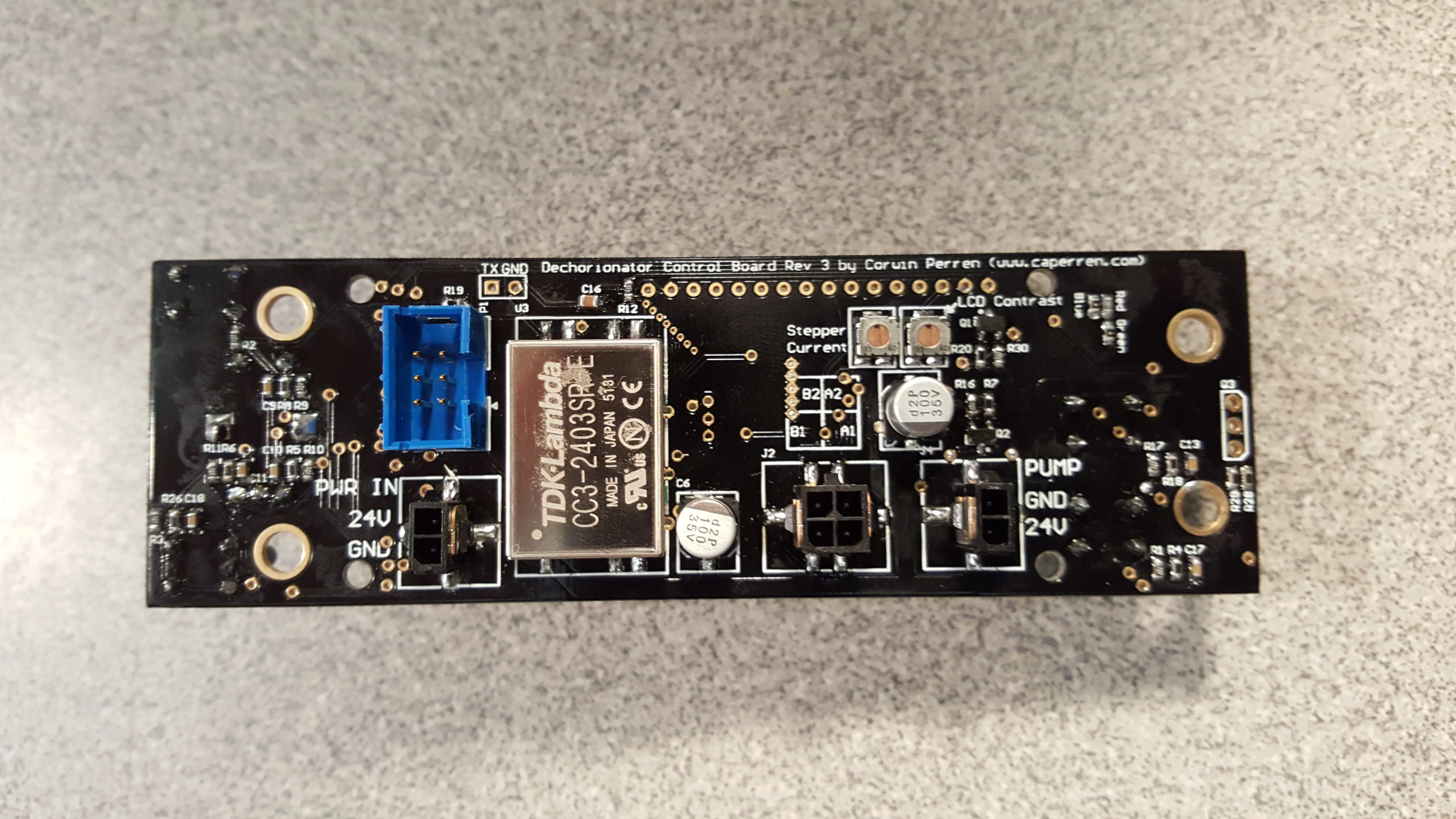
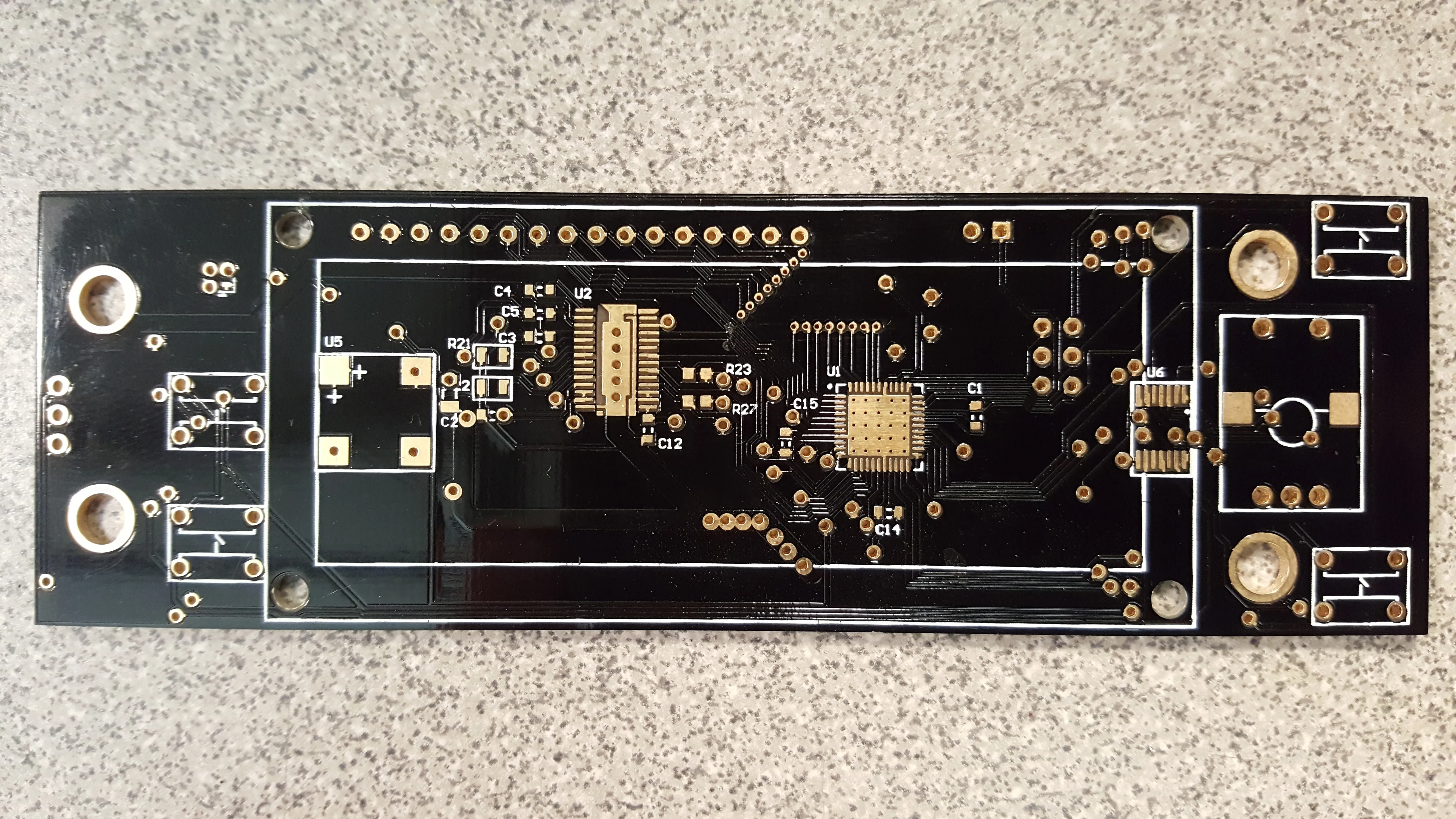
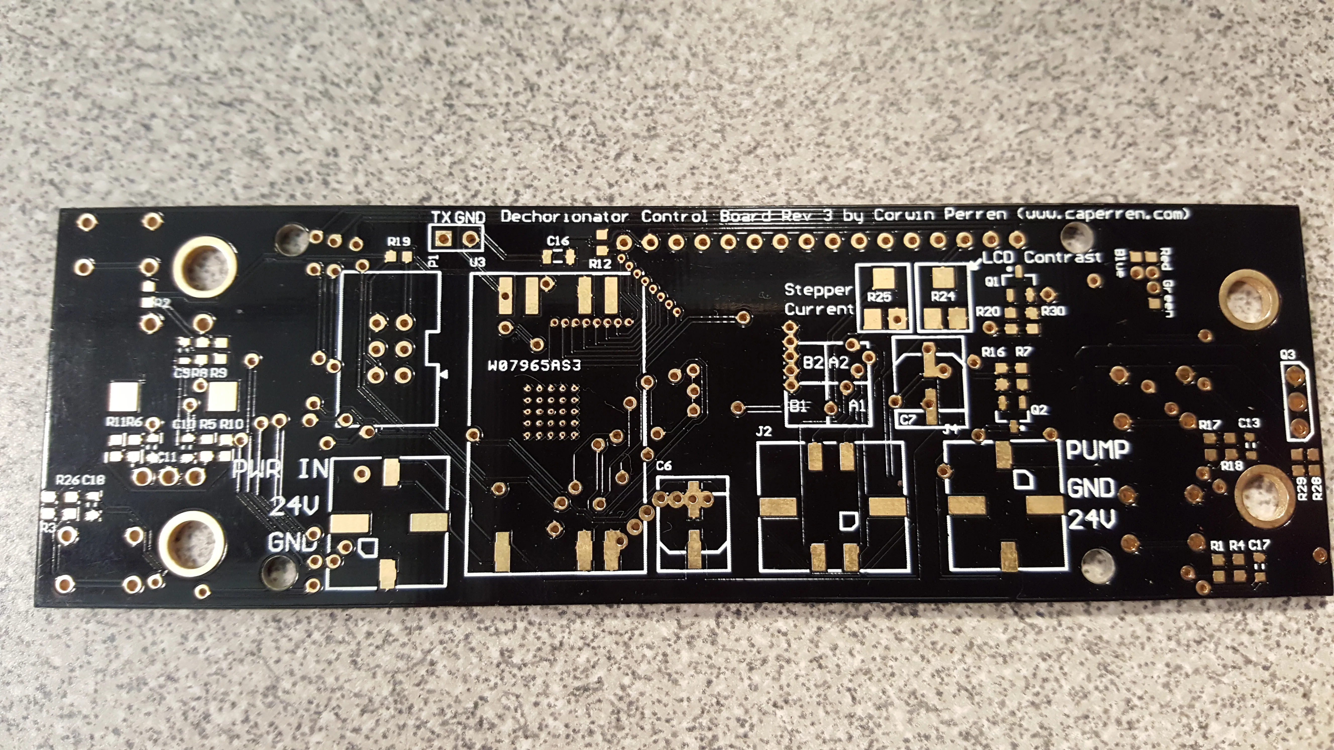
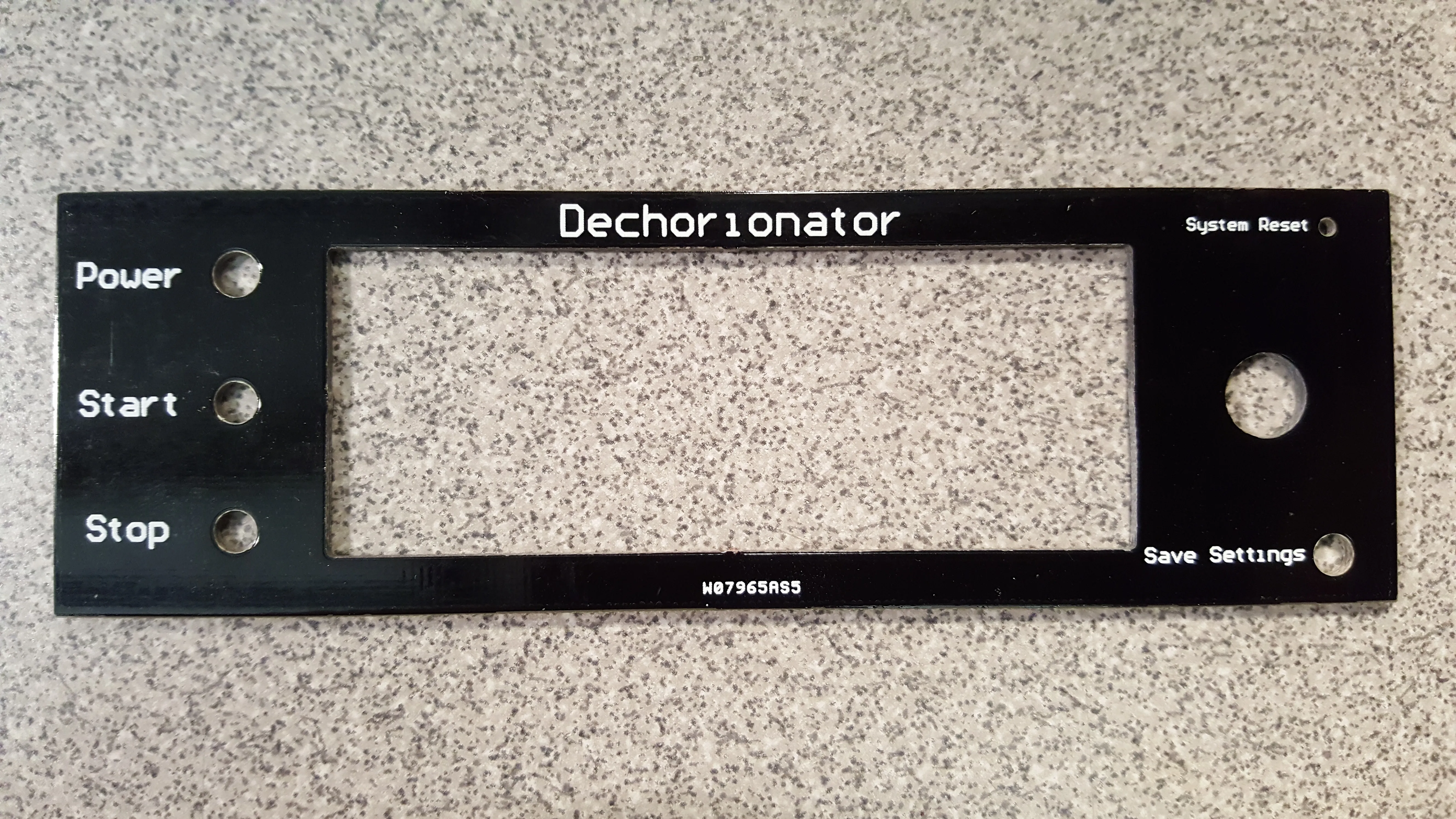
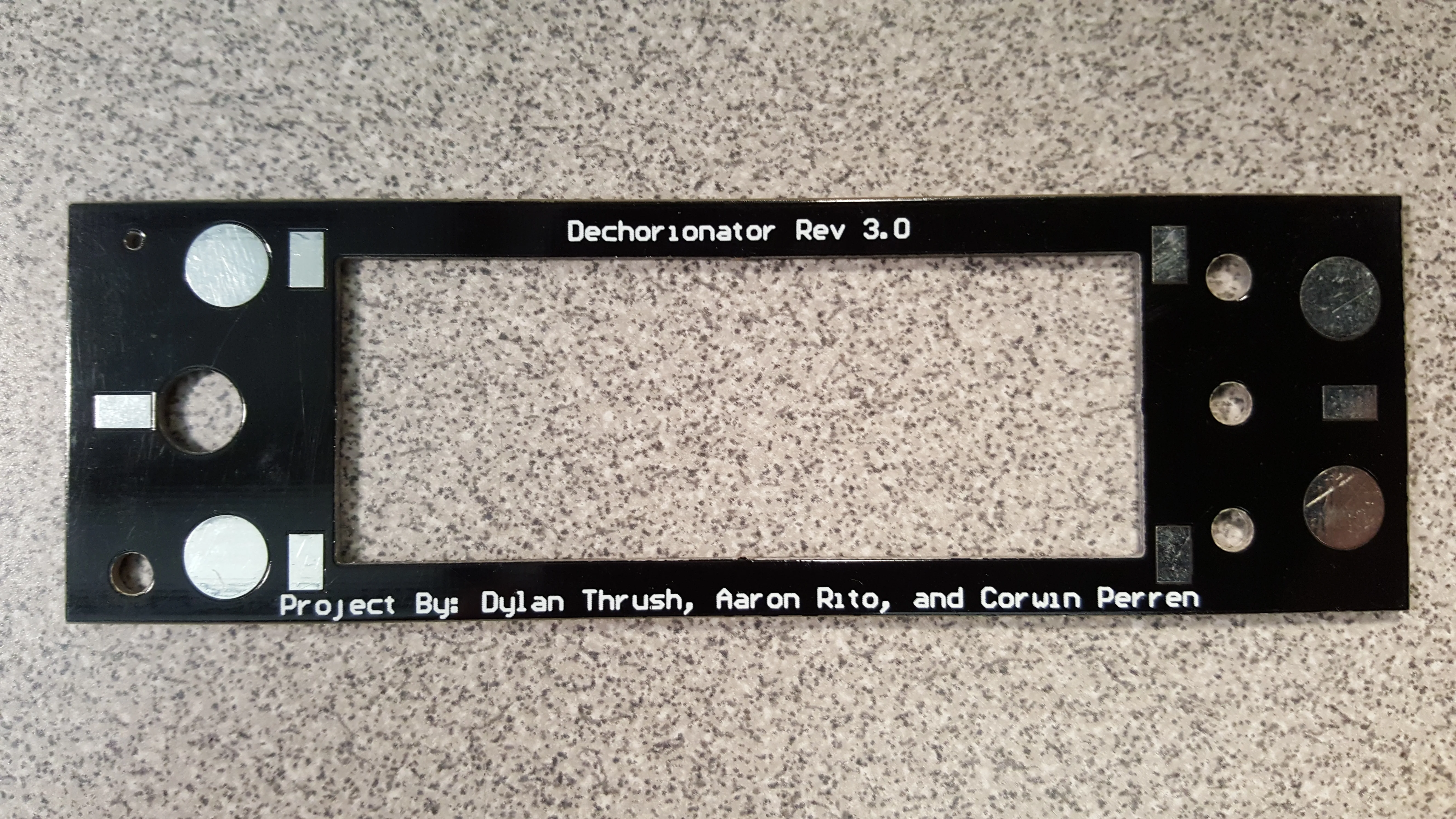
With the proof-of-concept design functional, I began a redesign of the
control PCB to replace the existing control panel and drive circuitry
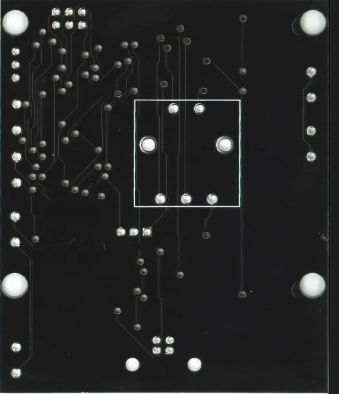
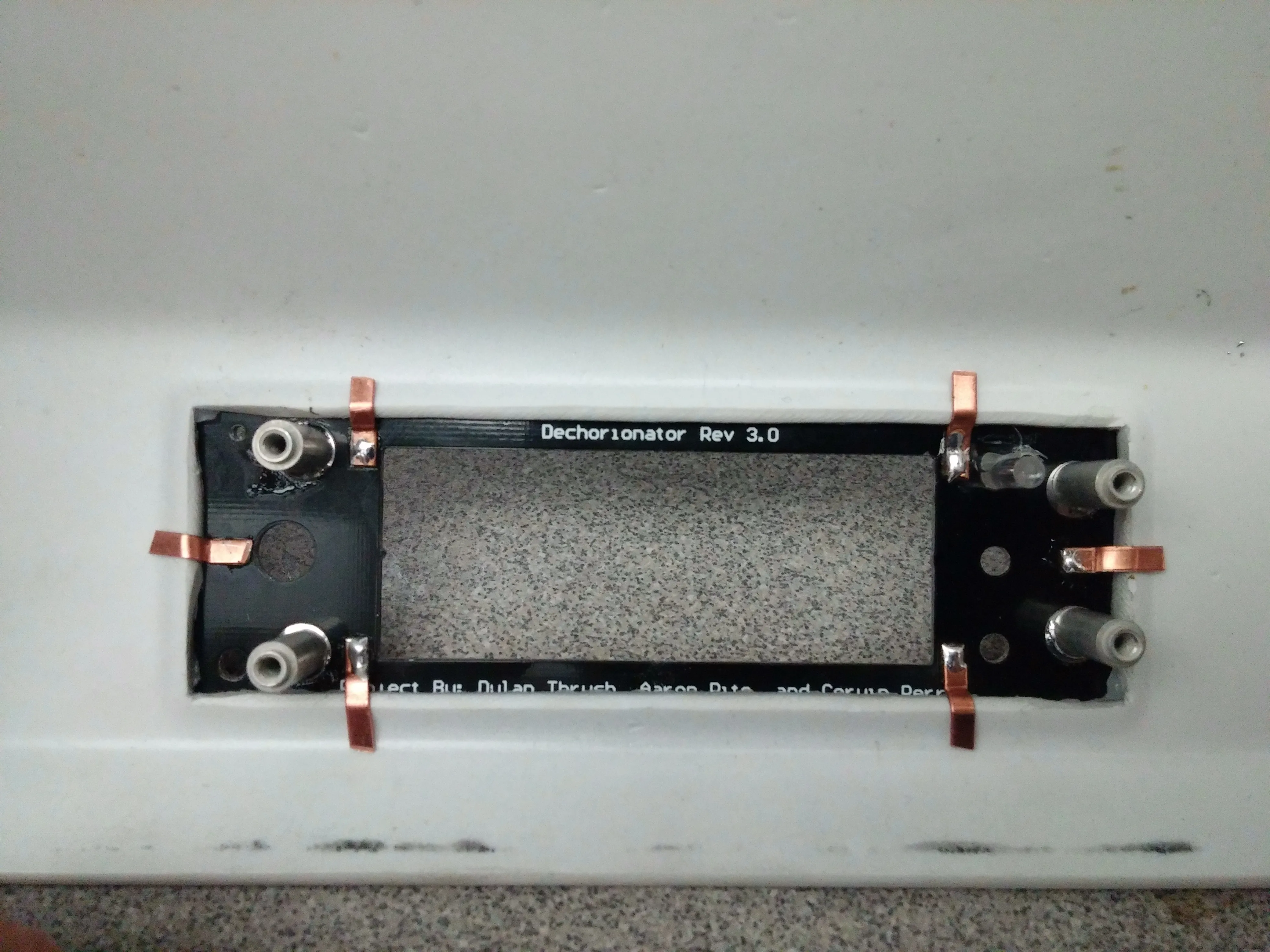
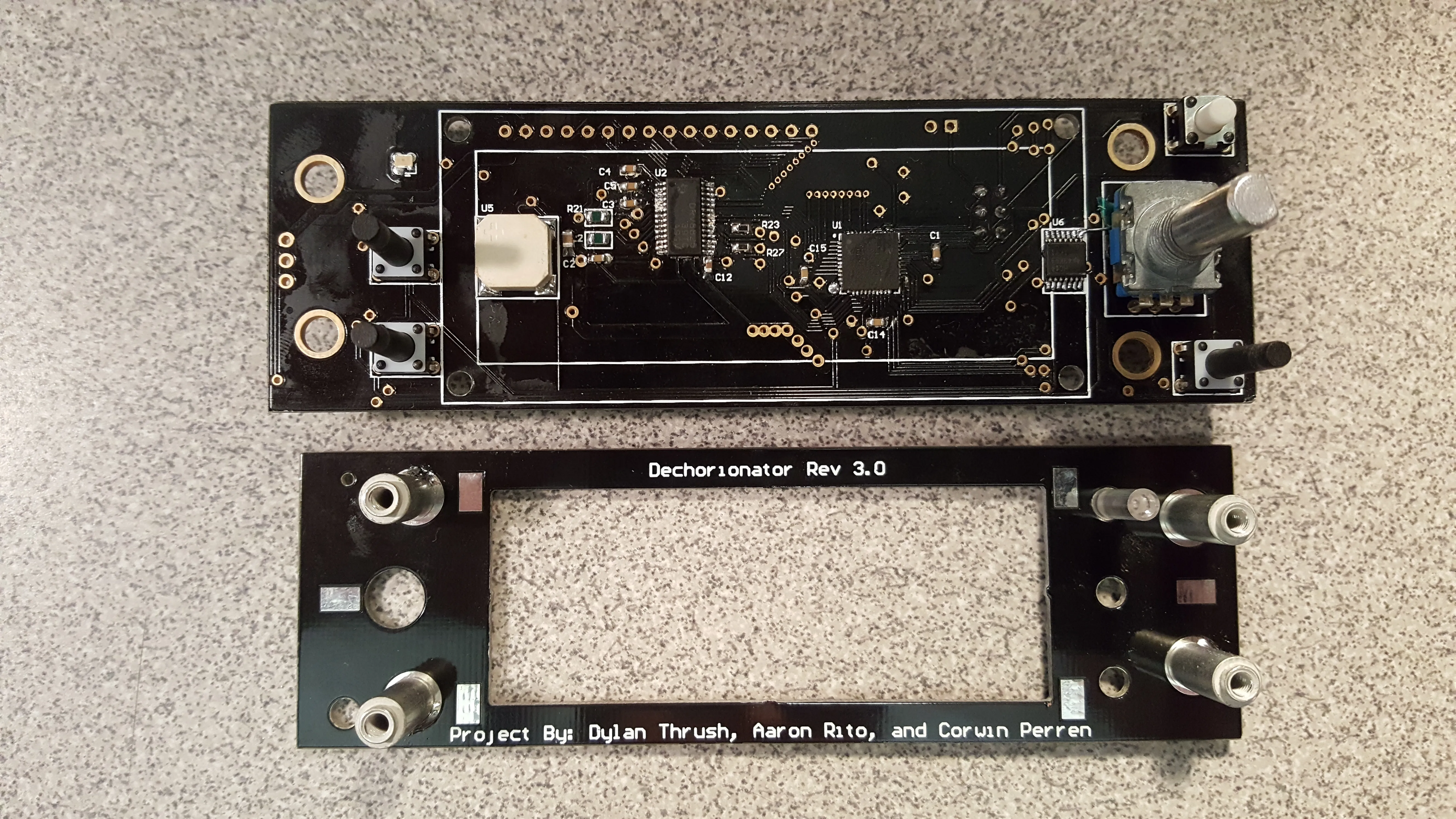
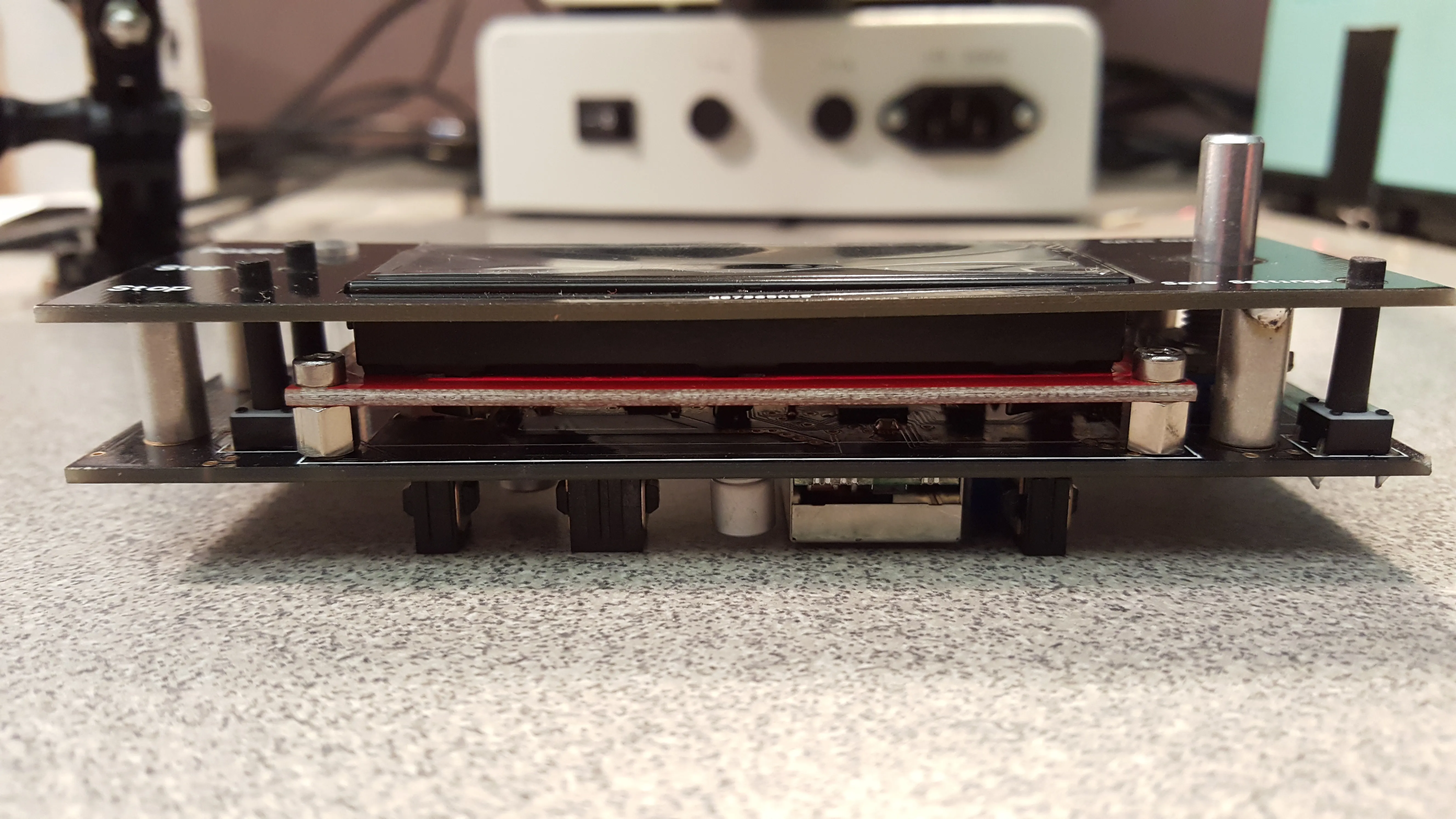
from the ELMI shaker (revision: 3.0.0). The existing control circuitry
had a unique assembly design that I'd not encountered before, using a
PCB with solderable standoffs as the front panel, and soldered copper
strips as retention tabs. I was so fascinated by the design that I
decided to emulate it. Check out the images at the end of the reel above
to see how this unique assembly was put together! Around the time that
the PCBs were ready, we'd hired a new engineer, Aaron Rito, who I tasked with writing the firmware while providing input and
guidance.
Over the next few months, many revisions were made to the firmware, as
well as mechanical designs for the showerheads and water manifold. Dylan
also had a final design for the top-plate milled out that looked
beautiful. Once those changes were complete, we provided the prototype
unit to the researchers, along with documentation on how to use the
tuning values. They then spent a few weeks running the new dechorionator
alongside the old ones, while tweaking these parameters until the
performance matched. We then built up four more units, and pre-flashed
them with this configuration. Three of these went into the lab, where a
total of four of our new dechorionators sat on the same table where just
two prior-generation ones used to live. It even had additional space for
pre and post prep work on the petri-dishes! The last one I installed in
a partner lab on the east coast after flying there with the head of the
lab, Robyn Tanguay and deputy director, Lisa Truong.
Printed Circuit Boards
Dechorionator
Control board which provides motion and water flow control, along with user control and monitoring
Revision: 3.0.0
2015-08-30
Revision: 1.1.0
2014-05-10